
In 1972, a draft FDA guide for large volume parenterals introduced the six-diameter rule for dead legs, and many engineers still size branches around it more than 50 years later. Since then, however, regulators have tightened their expectations considerably. EU GMP Annex 1 now treats any non-circulating pipe longer than three internal diameters as a dead leg, while ASME BPE pushes designers closer to 2D. As a result, a water loop in pharma can look compliant on paper yet still hide stagnant branches where biofilm settles and microbial counts slowly rise. Inspectors understand this gap well, so they rarely stop at the main loop; instead, they trace each point of use, sample valve and forgotten tee. For this reason, dead leg control has become a central question of pharmaceutical engineering rather than a drafting detail. This article therefore examines how branch limits, turbulent flow, sanitization and validation data work together to keep the loop defensible during inspection.
Table of Contents
Inside a Water Loop in Pharma from Tank to Point of Use
Every pharmaceutical water system begins its distribution journey in the storage tank. From there, a sanitary pump drives water through the supply line, past each point of use, and back to the tank through the return line. In this way, the water never stands still, which reflects the WHO expectation that distribution systems run as loops with continuous circulation. Meanwhile, production teams draw water at points of use only when a process needs it, so the loop must hold its flow and temperature steady even at peak demand. However, not every loop controls microorganisms in the same way. A WFI loop usually runs hot, and EU GMP Annex 1 cites constant circulation above 70 °C as an example of effective control. By contrast, a purified water loop often operates at ambient temperature and therefore relies on scheduled sanitization with hot water or ozone to keep biofilm from taking hold.
Where Inspectors Start When They Walk a Water Loop?
Inspectors rarely begin a water system review at the desk. Instead, they carry the as-built drawings into the plant room and compare them, line by line, with the pipework installed. Along the way, they look for branches that never reached the drawings, valves that sit too far from the main loop, and sample points placed where water rarely flows. They then check whether sanitization records cover every branch and point of use, not just the main circuit. This hands-on approach reflects WHO guidance, which expects a physical tour of visible pipework and user points during inspection. Moreover, EU GMP Annex 1 ties water systems directly to the site’s contamination control strategy and expects documented slopes, diameters and lengths across the system life cycle. In practice, a single mismatch between paper and pipe often tells an inspector more than any validation summary can.
Dead Leg Control Starts on the Drawing Board
Most dead legs are born long before the first weld. In fact, they usually appear when a designer adds a sensor tee, a future connection or a sample point without checking how far it sits from the flowing main pipe. Once the system is built, however, removing that branch means cutting, rewelding and requalifying part of a validated loop. For this reason, WHO guidance asks manufacturers to measure and calculate areas of possible dead legs at the design stage, while EU GMP Annex 1 expects slopes, diameters and lengths to stay documented throughout the system life cycle. In other words, regulators treat branch geometry as qualification evidence rather than a drafting preference. As a result, every line on the isometric drawing becomes a claim the loop must later prove in operation.
The four design rules below show where a water loop wins or loses that argument, starting with branch length and ending with the steel surface itself.
- How Many Pipe Diameters Is Too Many (Available PDF)
- Turbulent Flow from Supply to Return Line (Available PDF)
- Zero Dead Leg Valves at Points of Use (Available PDF)
- Slope, Drainability and the Surface Under the Water (Available PDF)
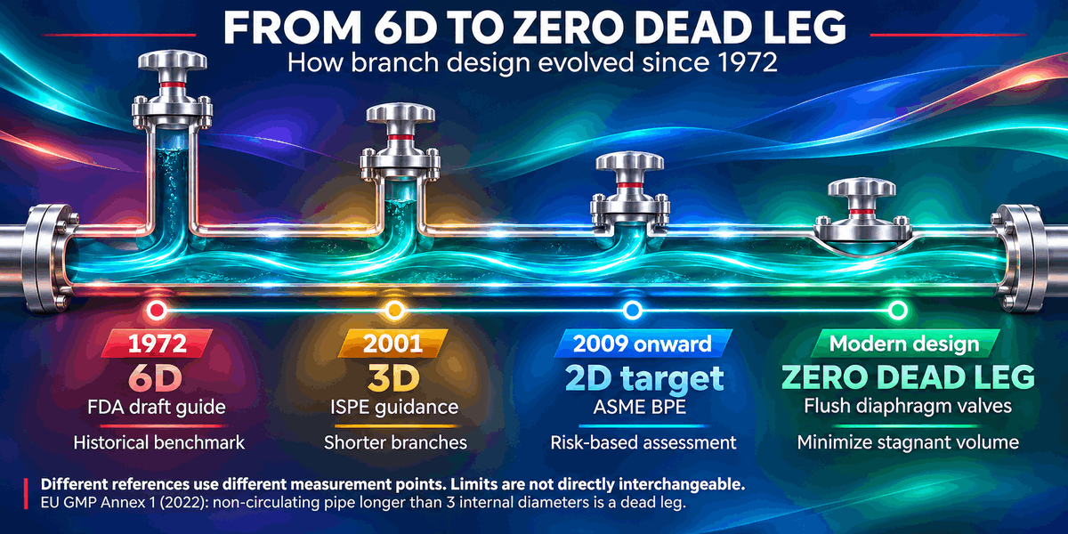
The infographic below maps how dead leg limits tightened from the 1972 six-diameter rule to today’s zero dead leg designs, helping engineers see why older branches now draw closer inspector scrutiny.
How Many Pipe Diameters Is Too Many (Available PDF)
Few numbers in water system design spark as much debate as the dead leg limit. The 6D rule first appeared in a 1972 FDA draft for large volume parenterals, and it soon became an industry habit. However, later research at Dublin City University found stagnant water at the end of 6D branches, while 2D branches reached full loop temperature. Since then, ISPE, WHO, ASME BPE and EU GMP Annex 1 have each set their own benchmark. Moreover, these rules measure from different points, so the same branch can pass one standard and fail another. For this reason, inspectors now expect a measured, risk-based justification rather than a quoted rule.
The table below compares the main dead leg criteria side by side, showing where each limit comes from, how it is measured and what it means during an inspection.
| Source (Year) | Dead Leg Limit | Measured From | Inspection Takeaway |
|---|---|---|---|
|
FDA LVP draft (1972), later adopted in the FDA water system inspection guide (1993) |
6D |
Centre axis of the main pipe |
Written for hot 75–80 °C loops; hard to defend for new designs |
|
ISPE Baseline Guide Water and Steam (2001) |
3D |
Wall of the main pipe |
Long-standing industry benchmark; drawings must show the measuring point |
|
ASME BPE (2009 onward) |
2D or less |
Inside wall of the main pipe |
A design target, not an absolute rule; recent editions use a risk-based definition |
|
EU GMP Annex 1 (2022) |
Non-circulating pipe longer than 3 internal diameters |
Not specified |
Longer branches count as dead legs and need risk control |
Turbulent Flow from Supply to Return Line (Available PDF)
WHO guidance links microbial control to turbulent flow, with a Reynolds number above 4000 as evidence. Because higher loop velocity improves heat reaching dead legs, the return line must stay turbulent even at peak demand.
Zero Dead Leg Valves at Points of Use (Available PDF)
WHO guidance recommends zero dead leg diaphragm valves wherever possible, since every point of use can trap stagnant water. Sample valves and sensor tees deserve the same scrutiny, as contamination often starts where water leaves the loop.
Slope, Drainability and the Surface Under the Water (Available PDF)
A water loop must drain completely, so EU GMP Annex 1 requires sloped piping that provides full drainage and avoids dead legs. Equally, orbitally welded 316L stainless steel with a smooth, passivated internal finish leaves biofilm fewer places to settle.
Heat, Ozone and the Fight Against Biofilm
No water loop stays clean on its own, so every biofilm strategy begins with a choice between heat and chemistry. Hot water sanitization remains the classic route, and USP 1231 now names 65–80 °C as the most common range instead of the old “at least 80 °C” rule. However, a lower temperature only works when every cold spot, including outlet valves off the main loop, still reaches a lethal temperature. Ambient purified water loops, by contrast, often rely on ozone sanitization, which suits cooler systems but must be fully removed before the water reaches the process. Meanwhile, hot WFI loops held above 70 °C stay far less vulnerable to microbial growth. In both cases, EU GMP Annex 1 expects sanitization on a predetermined schedule and again after out-of-limit results. Therefore, the right frequency comes from validation and trend data, not from calendar habit.
The Data Trail Inspectors Follow After the Walkdown
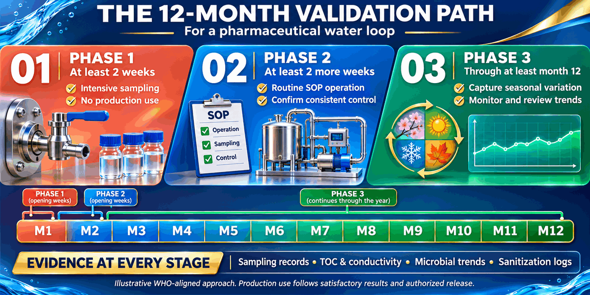
Once the walkdown ends, inspectors turn to the data, because a water loop proves its control on paper long before it proves it in product. First, they review the three-phase validation: at least two weeks of intensive sampling with no production use, a further two weeks under routine SOPs, and then monitoring that continues to at least 12 months to capture seasonal change. Next, they compare the sampling plan with the drawings to confirm that every point of use and the end of the loop appear in it. They also look closely at alert and action levels, since these limits should come from the system’s own historical data rather than generic numbers. Meanwhile, online TOC and conductivity readings show whether the loop stays stable between laboratory results. Finally, inspectors usually request the validation report, trend reviews, out-of-limit investigations, sanitization and maintenance logs, calibration records and the change control history for every loop modification.
The infographic below maps the three validation phases from first sampling to the 12-month system review, helping teams see when water can enter production and what evidence each phase must deliver.
Final Words
Recent enforcement shows a clear shift: regulators no longer treat water problems as a utilities issue, but as a test of the entire quality system. In a 2025 warning letter, for example, FDA cited a manufacturer for leaving 51 out-of-limit or out-of-specification water results uninvestigated over roughly 14 months, while staff simply resampled until the results passed. In other words, the weakest point was not the pipework alone, but the decisions made around its data. A compliant water loop in pharma therefore rests on three linked controls: justified branch limits, sanitization that reaches every point of use, and trend data that someone actually acts on. Teams that connect these controls before the next inspection will spend far less time defending their system during it.

Qualification and Validation for GMP Systems
Our team supports the planning, execution, and maintenance of qualification and validation activities, including IQ, OQ, and PQ, to keep GMP-regulated systems compliant and under control.
FAQ
No, not for new designs. The 6D rule comes from a 1972 FDA draft written for hot 75–80 °C loops, and it measures from the centre of the main pipe. Today, ISPE uses 3D, ASME BPE targets 2D or less, and EU GMP Annex 1 treats any non-circulating pipe longer than three internal diameters as a dead leg. Inspectors therefore expect every branch to be measured, documented and risk justified.
No fixed interval applies; validation and trend data must set the frequency. WFI loops held above 70 °C are largely self-sanitizing, while ambient purified water loops need scheduled hot water sanitization at 65–80 °C or ozone sanitization. EU GMP Annex 1 also requires additional sanitization after out-of-limit results.
Inspectors typically request the three-phase validation report covering at least 12 months, the sampling plan, the rationale for alert and action levels, TOC and conductivity trends, out-of-limit investigations, sanitization and maintenance logs, calibration records, and change control for every loop modification.
References
- WHO TRS 1033 Annex 3: Good Manufacturing Practices for Water for Pharmaceutical Use
- Pharmaceutical Water Systems: A Thermal-Fluid Analysis of Pipe Dead-Legs
- A Thermal-Fluid Analysis of Piping Dead-Legs in High Purity Water Systems
- ECA Academy: The Truth about the 3D/6D Rule
- FORCE Technology: Dead Legs in Piping Systems
- ECA Academy: Is the Sanitization Temperature for Water Systems Too High?
- European Pharmaceutical Review: FDA Warning Letters on Contamination Control

Marco Klinger is Head of Quality Services at Zamann Pharma Support, where he leads consulting teams through complex regulatory and quality-driven projects. He brings more than 15 years of hands-on compliance experience across regulated industries. His work includes close collaboration with companies such as Reckitt, Sanofi, Biotech, Biotest, and others. Marco has deep expertise in medical device development, aseptic manufacturing, and the design, implementation, and management of complete quality management systems within GMP-regulated environments.